Outdoor Ground Vehicle Software Test Platform (Tempestas) 2018
Project Description
After the University Rover Challenge I was left with a desire to play more with outdoor autonomous navigation, especially with a robot that has an ability to go over a certain size/type of obstacles. Without the teams rover or $17,000 of money to make my own I decided to develop a low cost platform to test software. The price point I was aiming for was about $500 but when it's all said and done it will probably be closer to $600-$700. This is designed to be a fully ROS capable robot when completed. It is currently in the manufacturing stage.
Project Details
- Cost < $500
- Compatible with ROS
- Able to drive in outdoor environments
- Large enough to carry several kg of sensors and computers
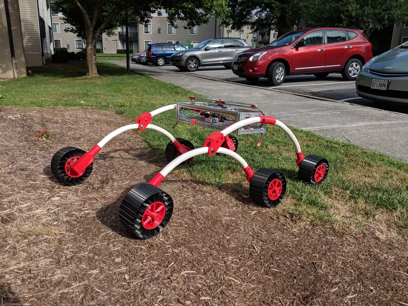
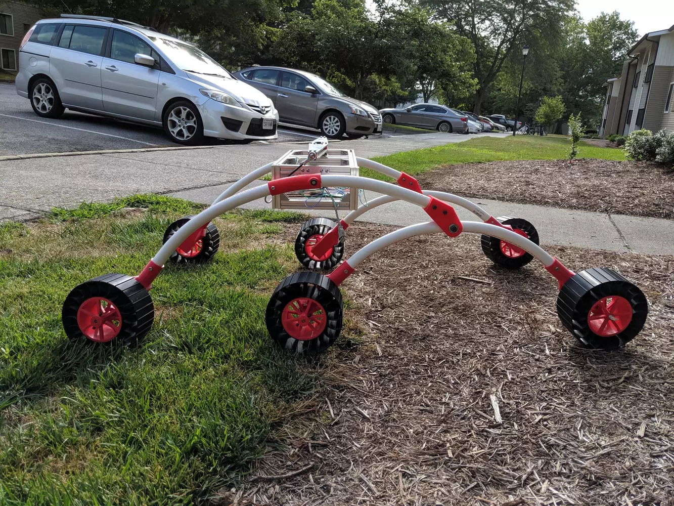
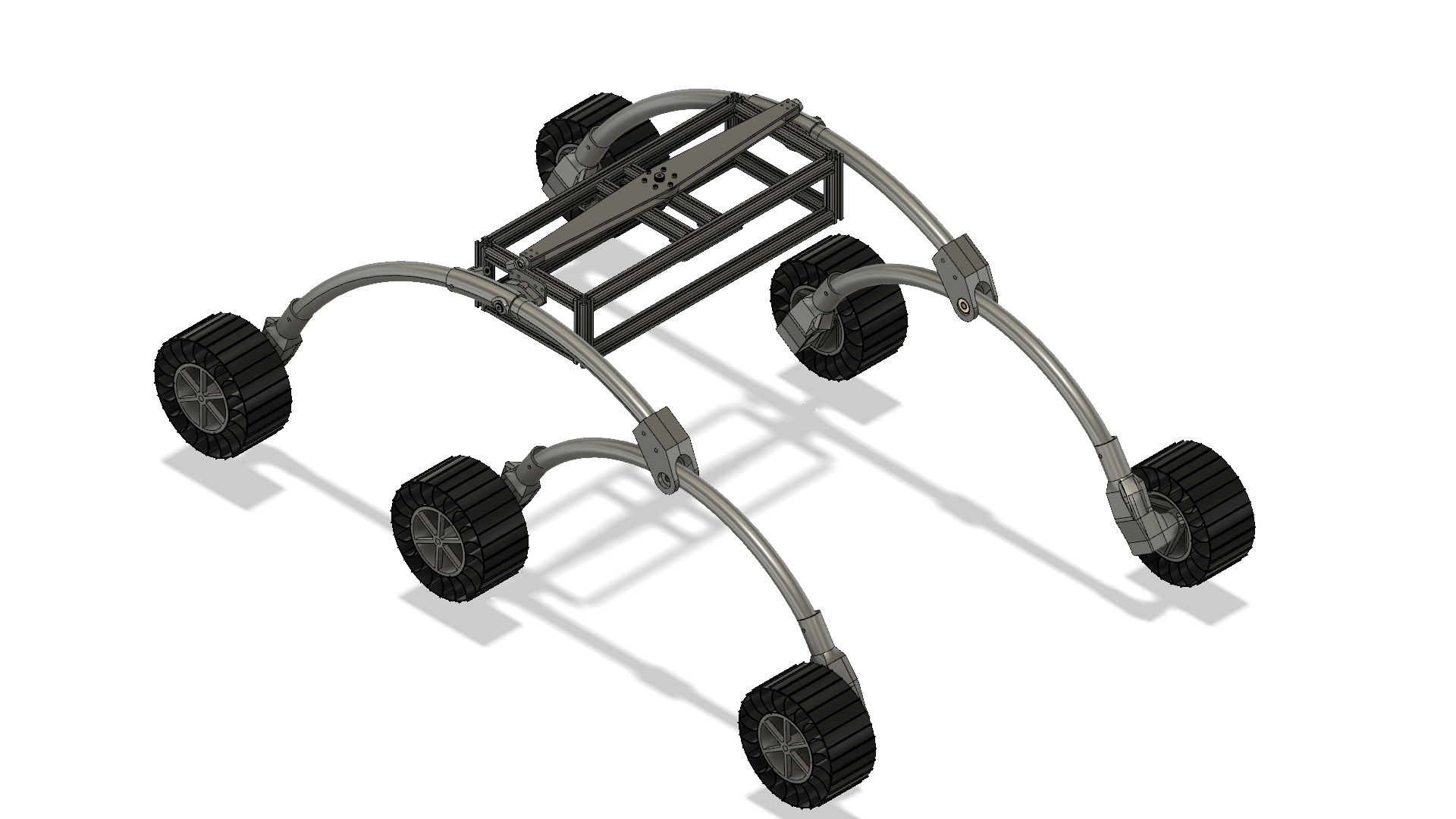
Design
The main driving factor for the design was low cost. This meant a lot of parts were made out of cheap and available parts. It also meant I tired to use 3D printing wherever I could since it allows for custom parts at a cheap price. The suspension for this robot is the traditional rocker-bogey which is a standard suspension for a lot of rovers. The overall proportions and shape of the wheel supports is inspired by one of the robots I saw at the University Rover Challenge Competition. The long suspension allow for good ground clearance. They are made of PVC pipe as it is light, cheap, strong, and flexible which puts some flexibility in the suspension. The chassis is made out of 20/20 as it is very easy to work with, it is cheap, and it allows for quick modifications. One of the more interesting things of the robot is the custom wheels I designed and manufactured. The outer part of the wheel that makes contact with the ground is made out of 3D printed TPU which is compliant. The inner part is 3D printed out of PLA. The differential bar is made out of a flat plate of aluminum with 3D printed spacers.
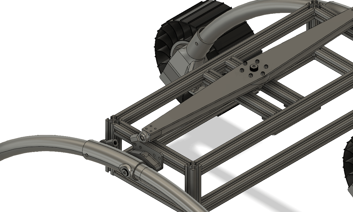
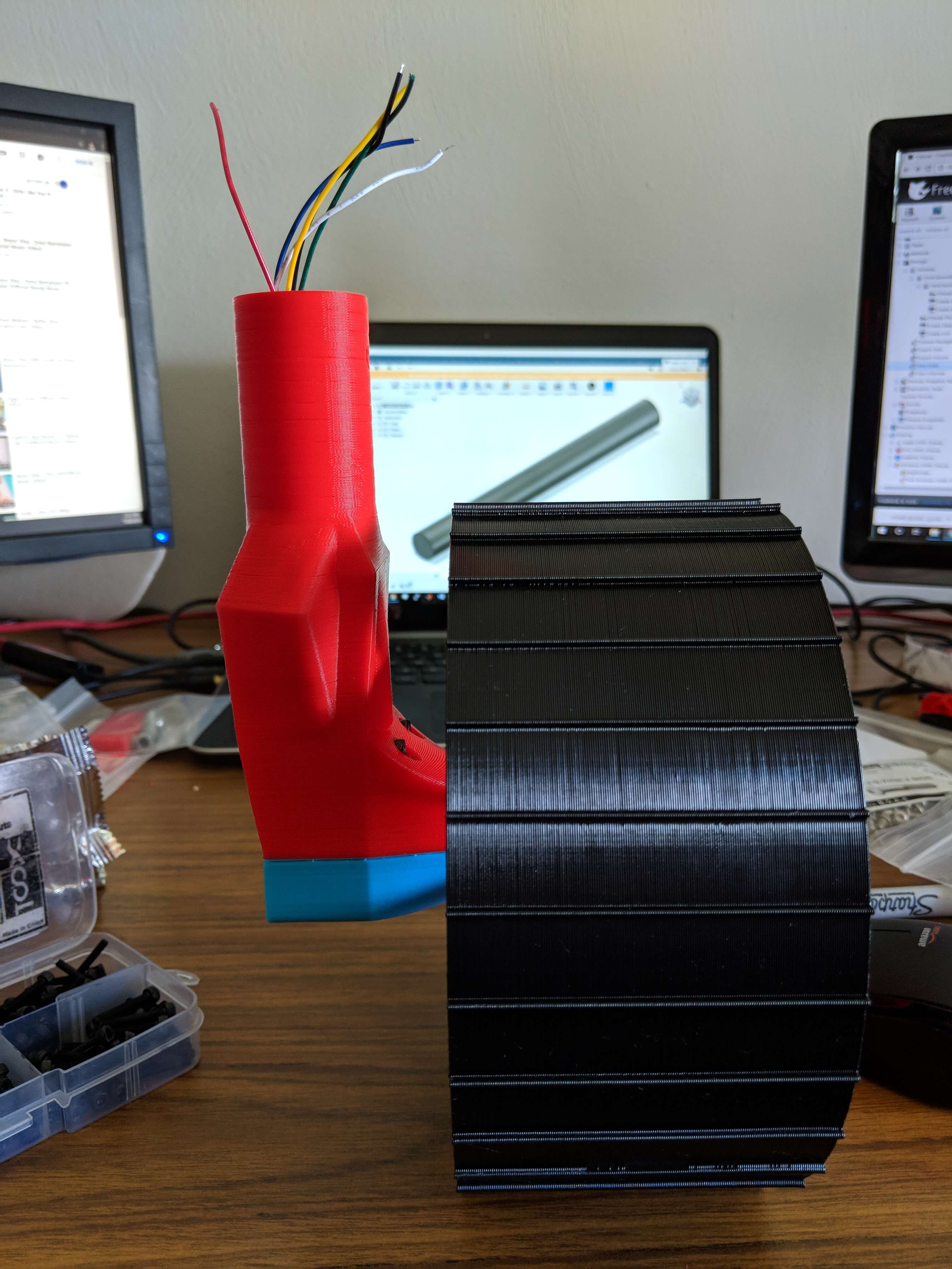
Wheels
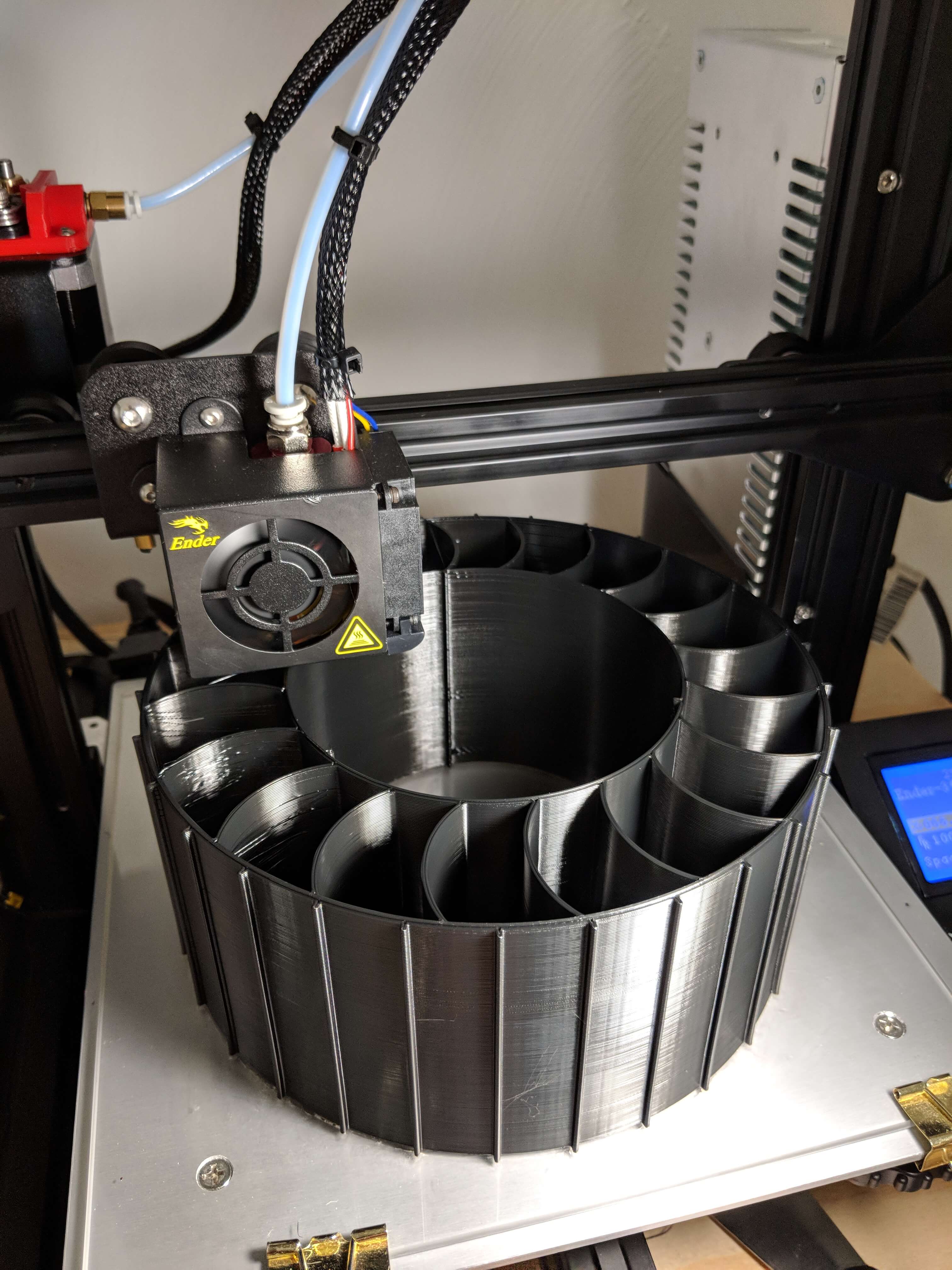
One of the biggest things we debated for the University Rover Challenge was what wheels to use. The lack of information and variety of wheels available eventually drove us to make custom wheels. From this I decided that I wanted to also make my own wheels but since one of the themes of this project was 3D printing I decided to look at 3Dprinting them. The two part design allows for faster printing as the TPU prints very slowly and for a good interface to the wheel axle. The shape of the flexible part is designed to maximize deflection while maintaining strength. The inner part is designed to maintain strength, maximize manufacturability, while minimizing weight.
The most challenging part of the wheels was the actual manufacturing. Despite what I read online about the "relative" ease of printing TPU it took me several weeks to get the wheels made. Most of my issues were related to the extrusion of the TPU. Since it is more flexible it likes to sneak out of the filament path right before the extruder. This was fixed with some modifications to the filament path. The issue that caused the most trouble was what appears to have been a clogging of the nozzle anytime TPU was left in the nozzle to cool. This meant a new nozzle had to be put in the printer to fix the issue. I got around this in the end with never stopping printing once I had a wheel printing working. This meant my printer printed straight for 102 hours (17 hours each * 6 wheels). This also meant I had to remove the wheel and restart the printer at every hour of the day and night.
In the end the wheels turned out great. I will be interested in the future to maybe address more of the problems I experienced with printing TPU.
Chassis
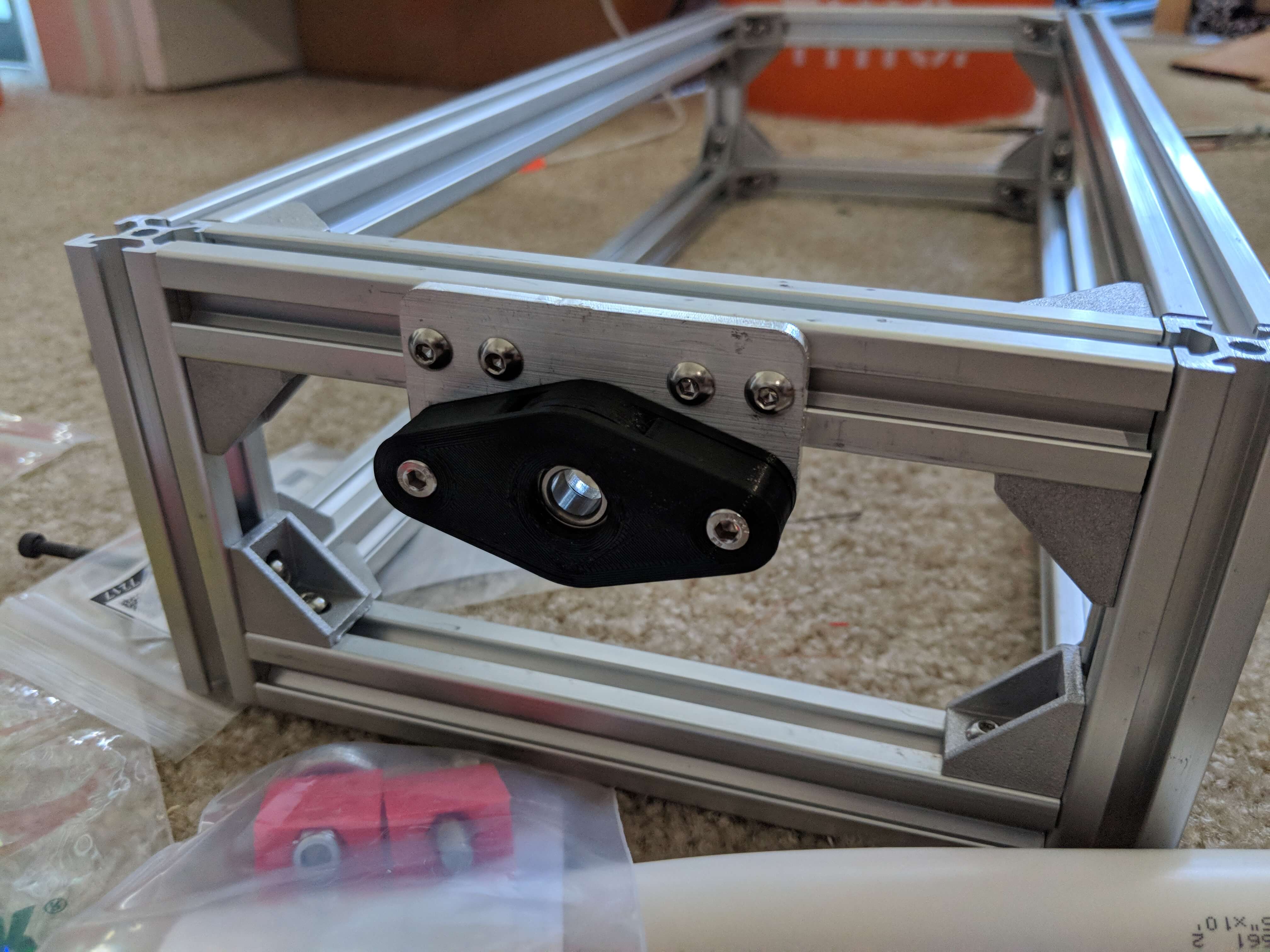
Manufacturing the chassis was pretty straight forward. The 20/20 parts went together fine. I do think the 20/20 might be slightly overkill. I wanted something smaller like 15/15 but the availability/price of it and connectors was nowhere near the same as the 20/20.
The other interesting thing I have done with the chassis is that I cut my first aluminum parts on my CNC router (X-carve). Since it is mainly a wood cutting router this was new territory for me but the parts turned out pretty good. Definitely not prefect but good enough for this application.
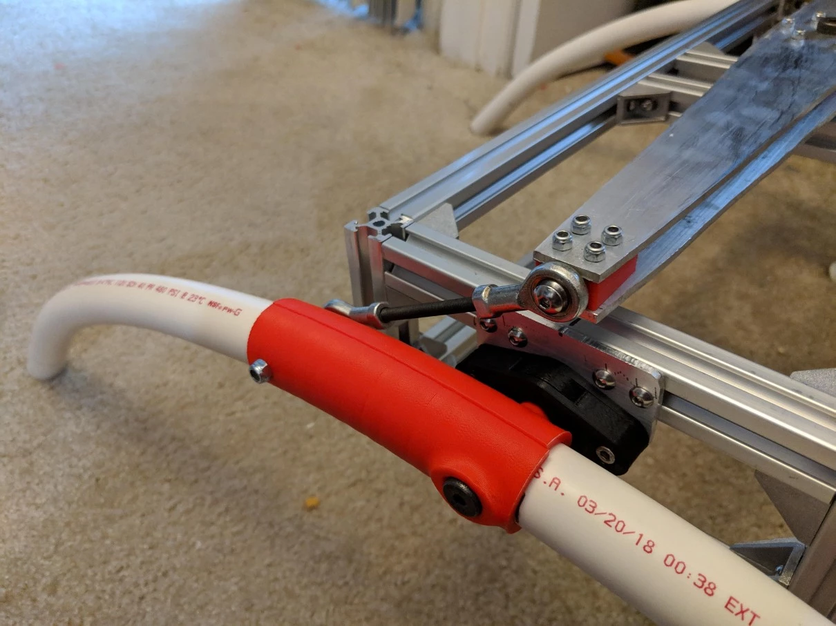
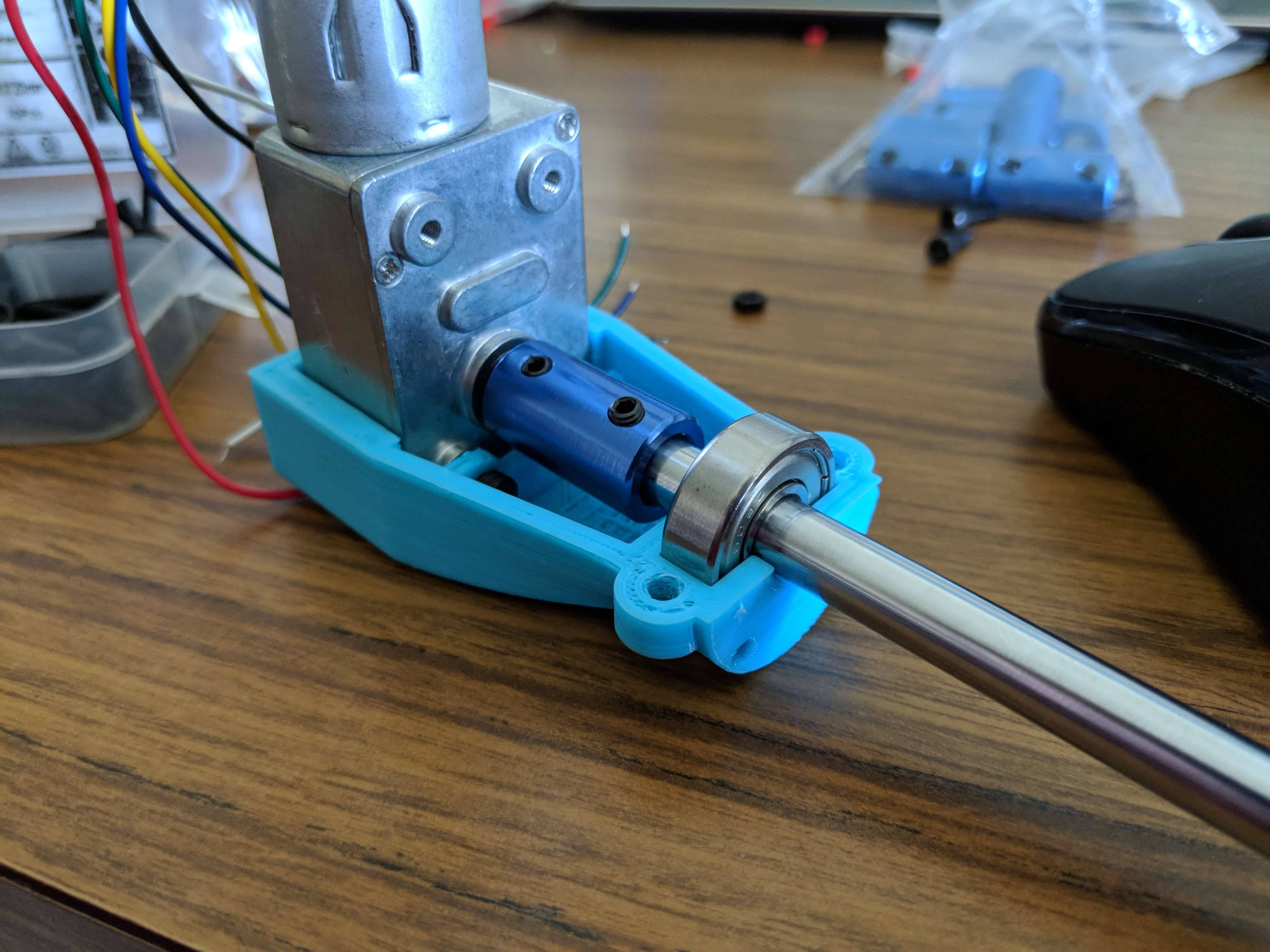
Motor Housing
Since mounting the motors requires some complex geometry I decided to use 3D printing to make the motor mounts. This allowed me to also enclose the motors and make the motors blend into the design of the robot well. The inside of the housing also provides support for the axle and contains the shaft coupler that connects the motor to the wheel axle. The housing is printed in two halves and is connect with M3 hardware.
Current Status
The mechanical part of the rover was completed and a temporary electrical system was installed to test the motors. The testing showed that the motors were too weak to properly use skid steer turning. The rover could drive forwards and backwards but could not turn. Doing some testing on the motors revealed that the actual torque was much less than the manufacture said. Future improvements would be to pick out new motors.