University Rover Challenge 2018
Project Description
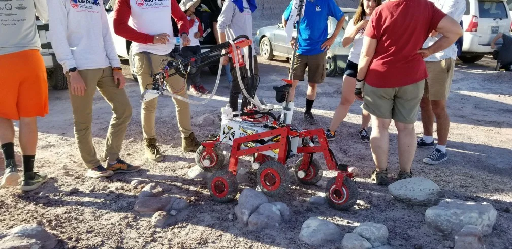
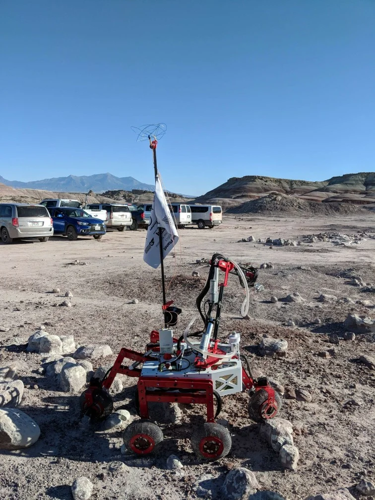
For my senior design project I worked on a team that designed and built a rover to enter in the 2018 University Rover Challenge held by The Mars Society. I served as the engineering lead and worked on a variety of subsystems as well as managing the technical aspects of the project. Our rover was one of 36 selected from a competitive pool of 95 teams to compete.
Project Goals
- Design rover to compete at 2018 University Rover Challenge (URC)
- Build rover for <$17,500 USD
- Become 1st Virginia Tech team to enter URC
- Pass competitive down-selection milestone and attend 2018 URC
Competition Tasks
Science Cache Task: Collect samples in field, Perform basic science evaluation with on-board instrumentation,Return a sample for further analysis Discuss results with judges.
Extreme Retrieval and Delivery Task: Pick up and deliver objects to astronauts in the field, Traverse varied & rough terrain.
Equipment Servicing Task: Perform several dexterous operations on a mock-up equipment system.
Autonomous Traversal Task: Autonomously traverse between markers over several stages, Traverse moderately-difficult terrain.
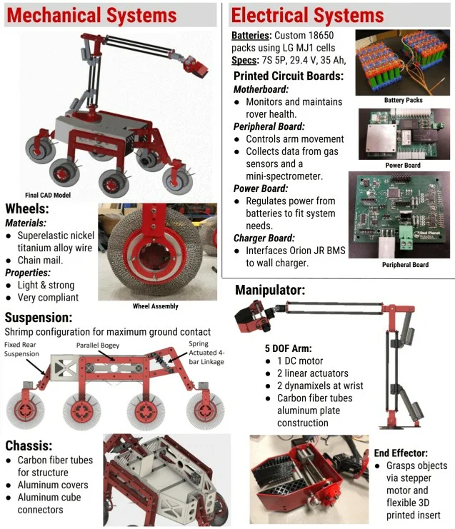
Hardware Overview
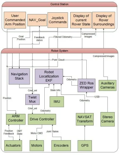
Software Overview
One of the areas I spent a lot of time was the software for the robot. The robot uses Robot Operating System (ROS) as the basis of the system. This allows us to use the great robot tools it has such as the TF tree, publisher subscriber architecture, and existing packages such as the state estimation/EKF software we used. The software is split between software that runs on the robot and the software that runs at the ground station.
The main areas of software I worked on was the low level drive controller and odometery feedback, GPS integration, IMU integration, stereo camera software, and the navigation stack. I will go into more detail about each below.
Computers On-board
- Main Control Computer - Raspberry Pi 3 B+
- Autonomy Computer - Nvidia TX2 (Navigation and Stereo Camera)
- Localization Computer - Raspberry Pi 3 B+ (GPS and IMU)
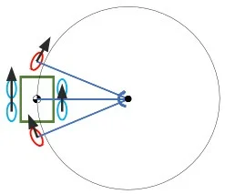
Shrimp Suspension Drive Controller
Since our suspension system in non conventional we needed to create a control scheme for the wheel speed and steering angles. Since the wheels on the side of the robot are configured in the same way as a skid-steer robot these wheels follow that same control law of wheel speed based on the angular velocity of the robot and the instantaneous center of rotation. Using the instantaneous center of rotation the wheel speed for both the front and back wheel can be calculated along with the steering angle for the front and back wheels.
With the math out of the way this was implemented in a python script that sent serial commands to our motor controllers and Dynamixels. This ROS node also ingested the wheel encoder feedback and converted it to the wheel odometery position estimate of the robot for use in the localization stack.
Stereo Camera Integration
One of the best hardware selection choices our team made was the selection of the ZED stereo camera as our primary obstacle detection camera. The camera was a great because the software that goes along with it worked out of the box. Setup was extremely easy since the manufacturer also made ROS drivers. Thus the main thing I had to do was integrate it into our software. The mapping software we used was RTABMap (Real time appearance based mapping). This software worked pretty well for us at generating the 3D point cloud that my navigation stack ingested. An example of the stereo camera being used on our software test platform with move_base if shown to the right.
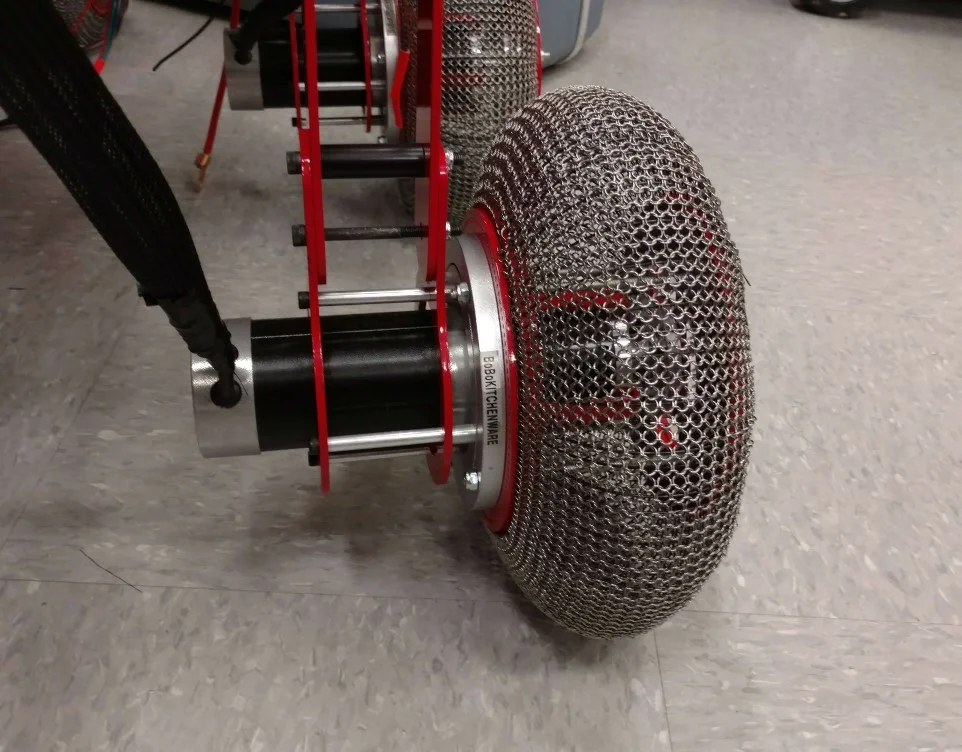
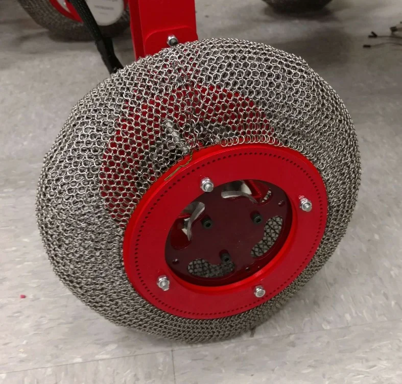
Custom Super-elastic Wheels
One of the most novel things on our robot was our wheels. We were inspired by the new wheels NASA had recently unveiled that use a super-elastic Nickel Titanium Alloy. I had looked at making ones similar to the ones we saw in the NASA video with spiraled wires but a quote from a Nitnol shaping manufacture made us realize that was way out of our price range (~$25,000 for a set of 6). Looking at them I realized they looked a lot like chain mail so I looked at buying industrial chain mail and using a U-shaped bent wire to provide the structure underneath the chain mail. Each wheel is comprised of ~100 wires clamped between two aluminum plates with 3D printed inserts to improve contact area in the clamp. The outside of this is covered in the chain main and secured on each side with floral wire.
Upon pricing the materials and building two prototypes we settled on the design you see. These wheels provide very good traction in sand and dirt as well as conforming well to the ground to increase traction. The only real downside we saw besides increased manufacturing complexity over buying wheels was we had some issues with wires breaking during use. This is most likely due to either the wires having too much prestrain from bending them into place during assembly or the quality of the Nitnol not being up to spec as it was bought from a Chinese supplier at a very reasonable price.